
The Motorola HC12 microcontroller for this robot as the group was already familiar with how it worked and how it could be programmed. The robot was programmed in C language using IAR VisualState V5.0 along with Metrowerks CodeWarrior V3.0.
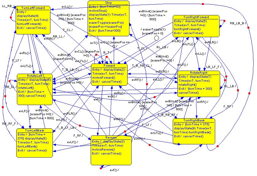
First of all a complete State chart was created for the robot using IAR VisualState’s Designer. This involved creating the nine states that the robot would be in which were; Stop, Forward, Reverse, Turn Left Forward, Turn Right Forward, Turn Left Back, Turn Right Back, Rotate Left and Rotate Right. The default state for the robot was the Forward State as it was expected that the robot would be driving forward most of the time.
The events and functions required by the system were created using the VisualState Designer’s Element Browser. Events for the system were a timer event and inputs detected from the six bump sensors and five light sensors. The timer event was used to ensure that the robot didn’t get stuck in a state. The action functions were mainly for the different ways the motors were being driven and for operating the servo motor to lift and lower the eraser. To assist debugging, there was a displayState action function that set a fixed value for each state that the robot was in. All these events were added to the state chart to trigger state transitions and the functions were added to their relevant states. Two external variables were also used: one was for the eraser position - whether it was up or down - and was used as a guard expression on state transitions in the Visual State diagram, and the other variable was for setting the default time duration for the timer.
Once a complete state chart was set up, VisualState’s Validator was run for interactive simulation of the state chart. Fortunately, despite the sheer complexity of the state chart and the numerous possible errors that were expected, the simulation worked smoothly and perfectly and no errors were detected with the state chart.
The next step involved generating the code from VisualState and using it with Metrowerks.
On the basis of the design created with IAR VisualState Designer, code was automatically generated for this VisualState Project by means of IAR VisualState Coder. The files with the code were then copied across to Metrowerks.
In Metrowerks, two files required altering - InputEventGernerator.c and Actions.c. - See Code Appendix
InputEventGenerator.c as the name suggests, provided code for detecting the inputs from the bump sensors and light sensors and generating events for them. The input from the bump sensors was debounced to ensure a stable input was being received. It was found that the light sensor input couldn’t have the same debouncing that the bump sensors did, due to oddities in the way the light sensors returned data.
Actions.c provided code for the actions the robot was expected to carry out - driving, lowering and raising the eraser and displaying the current state that the robot is in on LED display. The generated code proved to be quite handy as all the required functions’ prototypes were listed under the System1Action.h file.
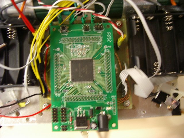
Metrowerks allowed easy, convenient and quick creation and use of Beans for configuring ports and using Pulse Width Modulation (PWM) for the dc and servo motors. Two BitsIO beans were used for the left and right motor and these allowed selection of the pins for driving the motors in the forward and reverse direction. These also provided a PutVal method where passing a value of 0x01 drove the motor forward and passing a value of 0x02 drove the motor in the reverse direction.
Three PWM beans were used for enabling the three motors. As aforementioned these beans were easy to use as all that was required was to set the period and starting pulse width. These also provided a number of different methods for setting the duty cycle.
It was decided that for the right and left motor, the duty cycle would be set using the SetRatio16 method where the ratio was expressed as a 16-bit unsigned integer number. 0-FFFF value being proportional to ratio 0-100%. Testing determined that a 60% duty cycle was appropriate for driving the motors at the desired speed. A value of 0x6666 was found to correspond to a 60% duty cycle. The motors run on a 60% duty cycle most of the time except for while turning where one motor runs slower than the other (at a 40% duty cycle i.e. value 0x9999). To operate the two dc motors, the PWM is first enabled, then the duty cycle is set and then the motors are driven forward or reverse as required.
For the servo motor, it was easier to think in terms of the time it would take for the servo to raise and lower the eraser and hence the setDutyUS method was used for expressing the duty cycle in micro seconds. The length of the pulse determined the position of the servo. On testing it was found that a range of 600?s - 1000?s corresponded to the two extreme positions of the servo.
VisualState and Metroworks made event driven programming fairly simple and easy for the successful operation of the robot.